LIN Decoder
The LIN Frame Format
In simple terms, the LIN bus message frame consists of a header and a response.
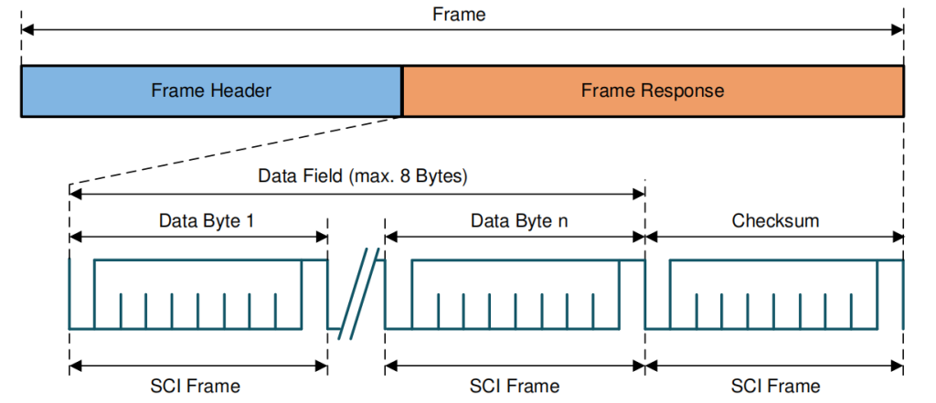
Typically, the LIN master transmits a header to the LIN bus. This triggers a slave, which sends up to 8 data bytes in response.
Header
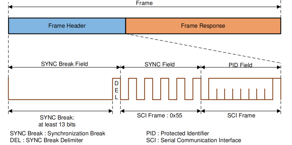
Response
LIN Decoding in HScope
Use the following settings:
- Input range: at least 16V
- Sampling rate: at least 100KSa/s
- Use the digital module to enable the LIN decoding
Sample of HScope decoded data:
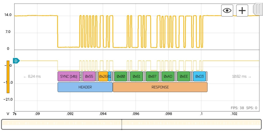
- In the HEADER part the
module IDis in YELLOW color. - Data fields are in GREEN color.
- Light BLUE fields are for parity and CRC control.
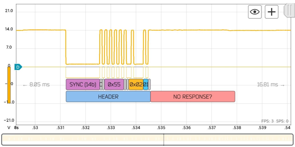
HScope LIN decoder performs automatically: LIN bus speed recognition, parity and CRC check. In case of problem the corresponding field will be in RED color:
What is LIN?
LIN bus is a supplement to CAN bus. It offers lower performance and reliability - but also drastically lower costs.
- Low cost option (if speed/fault tolerance are not critical)
- Often used in vehicles for windows, wipers, air condition etc..
- LIN clusters consist of 1 master and up to 16 slave nodes
- Single wire (+ground) with 1-20 kbit/s at max 40 m bus length
- Time triggered scheduling with guaranteed latency time
- Variable data length (2, 4, 8 bytes)
- LIN supports error detection, checksums & configuration
- Operating voltage of 12V
- Physical layer based on ISO 9141 (K-line)
- Sleep mode & wakeup support
- Most newer vehicles have 10+ LIN nodes