CAN Decoder
CAN (Controller Area Network) Bus is a serial protocol used in automotive and industrial machinery to allow microcontrollers to communicate with each other. It uses differential signalling (with signals named CAN H and CAN L) to increase noise immunity.
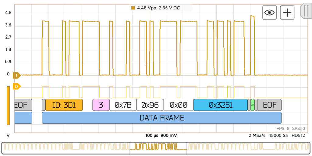
HScope can decode only the CAN-L signal.
Decoder Specifications
| Protocol | CAN 2.0 A and CAN 2.0 B (CAN FD not supported) |
| Signals | CAN-H |
| Max speed | Up to 1 Mb/s |
| Frame parameters | ID, DLC, Data bytes, CRC Sequence, CRC Delimiter, ACK Slot, ACK Delimiter |
Oscilloscope requirements
The oscilloscope sampling rate must be at least 3 times higher than the CAN speed. In case the CAN speed is 1Mb/s, you need to set the rate at least 3-4MSa/s.
Activating CAN Decoder
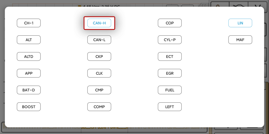
1. Assign the name to the channel that acquired CAN-L signal. This will create e digital signal in the Digital Module from the analog data.
2. Select the CAN decoder for the digital signal.
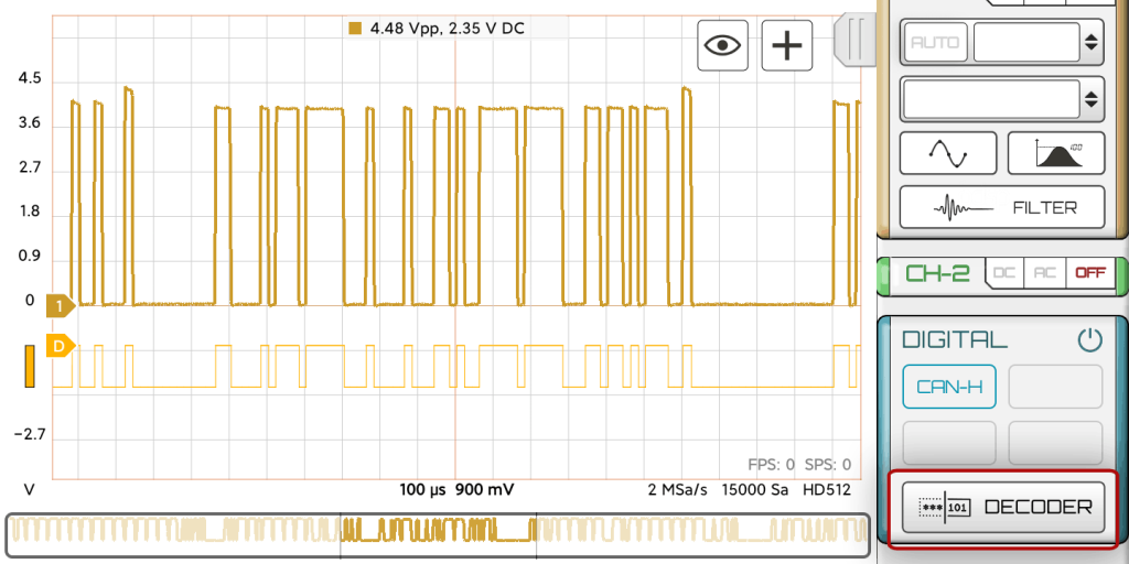
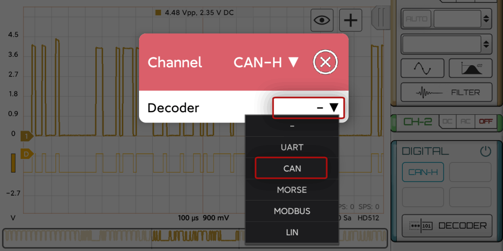
Now you should see the decoded data.
Fields: (all numbers in Hexadecimal format)
| Field name | Length (bits) | Purpose |
|---|---|---|
| Start-of-frame (gray) | 1 | Denotes the start of frame transmission |
| Identifier (yellow) | 11 | A (unique) identifier which also represents the message priority |
| Data length code (DLC) (pink) | 4 | Number of bytes of data (0–8 bytes) |
| Data field (white) | 0–64 (0-8 bytes) | Data to be transmitted (length in bytes dictated by DLC field) |
| CRC (blue) | 15 | Cyclic redundancy check |
| CRC delimiter (gray) | 1 | Must be recessive (1) |
| ACK slot (green or red) | 1 | Transmitter sends recessive (1) and any receiver can assert a dominant (0) |
| ACK delimiter (gray) | 1 | Must be recessive (1) |
| End-of-frame (EOF-gray) | 7 | Must be recessive (1) |
What is the CAN bus protocol?
The Controller Area Network (CAN bus) is a message-based protocol designed to allow the Electronic Control Units (ECUs) found in today’s automobiles, as well as other devices, to communicate with each other in a reliable, priority-driven fashion. Messages or “frames” are received by all devices in the network, which does not require a host computer.
Low speed CAN
Used for fault-tolerant systems that do not require high update rates. The maximum data transfer rate is 125 kbps, but the wiring is thus more economical than high-speed CAN. In automotive applications, low-speed CAN is used for diagnostics, dashboard controls and displays, power windows, etc.
High speed CAN
Used for communications between critical subsystems that require high update rates and high data accuracy (e.g., anti-lock braking system, electronic stability control, airbags, engine control units, etc). Data transfer speeds of high-speed CAN range from 1 kbit to 1 Mbit per second.
What is the CAN FD?
CAN FD is a “Flexible Data (Rate)” version of the CAN bus. The standard length of each message has been increased by 800% to 64 bytes, and the maximum data rate has been similarly increased from 1 Mbps to 8 Mbps. The “flexible” part refers to the fact that ECUs can dynamically change their transmission rates and select larger or smaller message sizes, based on real-time requirements.
Despite all of these advances, CAN FD is still completely backwardly compatible with standard CAN 2.0.